Main hull construction ³
(continued from page [ 2 ]This is part three about the construction of the main hull. At the bottom of this page the boat is almost ready to be launched. And that has become very necessary because the workshop will be sold. Now my final planning for the launch is April 1, 2018 and that is not a Fools' Day joke.
Preparations for the deck laminate
In connection with the placement of the high density foam inserts now is the time to think very seriously about the deck lay-out. During the whole build I have been pondering with a few different options about rigging and hardware.
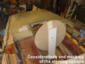
A deck stepped boom resolves the problem caused by lines (reefing lines, outhaul, mainsheet) coming from the boom and interfere with mast rotation. I made a mock-up to see how big of a problem this is and also studied a lot of steering's of the big 60' Orma Tri's. My conclusion is that it is not worth the extra trouble and the interference with mast rotation can be minimized by making the line exit in the boom a little more aft of the mast. So the boom will be mounted to the mast “the normal way” with the advantage that the boom induces the mast rotation.
I can see the advantages of the self tacking jib. However, there are some complications. The track crossing the daggerboard case interferes with the daggerboard and the length of the track is limited by the folding movement of the beam. Nevertheless (I'm getting older and looking for more sailing comfort) I have decided to go for the self tacking jib and I assume that I am able to resolve this in the future finishing phase of the build.
Furthermore I decided to make a curved track for the mainsail sheet traveler. Probably the traveler will be extended to the beams, but this is also of later concern. The mainsail sheet goes to the winch on the port side of the cabin roof. (*)
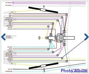
And finally I have designed a plan to organize all running rigging from mast to the winches on the cabin roof. With the above starting points and the running rigging plan I am now able to put in all high density foam inserts in all these places where hardware will be bolted down.
(*)Note: In hindsight, I made a different decision and built a more classic (read: straight) mainsheet traveler. More about this in this link.

Cabin windows
The content on this page follows the progress of the construction of the main hull in an almost chronological order. But making the cabin windows is carried out in several phases. Therefore you will find in the gallery several pictures actually belong at a later stage, but for completeness are added here.
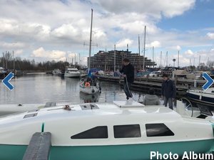
The design requires bolted windows, but I do not like that solution. Instead, I want to glue them into a rebate. The outside of the window is then about flush with the outside of the hull. Determining the size of the intended windows, also a little different from plans, was a challenge to get it right. Finally I found out that I get the best appearance when the length halfway the height of the window is about the same for all three windows.
The glazing material is smoke grey acrylic. The windows are curved in two directions and I prefer to make them pre-curved instead of pressing them in the right curve. So, first thing is to make a mold with the right curve in it. I did this by infusing a sandwich panel against the outside of the cabin wall. I outsourced the windows to a local specialized company, de bootruitenspecialist. They thermoformed the acrylic in an oven and used my molds to give them the right curves. The dimensions have been digitized and saved in their database. The result is fabulous and the windows fit perfectly.
Deck hatches
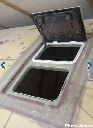
Well, it is a one-time opportunity so I choose for the difficult option of flush hatches, which I found in Lewmar as the most economical ones. I like fresh air and lightness and ordered one size 60 in the fore deck, two size 10 in the head and opposite passage way, two size 30 in the cabin roof and one size 54 in the aft cabin. Flush with the deck means also a water drain below the deck and that is an extra challenge to resolve.
In an earlier stage I made the escape hatch coaming. In this gallery you can see some steering's of the making of this part. When I made this part the dimensions were based on a heavy duty Lewmar model. Unfortunately, when I really needed the model, it was taken out of production. I found an alternative in the Vetus Magnus hatch which is also suitable for the A1 location in the lower part of the hull.
Aft cabin and cockpit construction

With respect to the vacuum infusion of the deck there is a natural separation between the deck and roof of cabin and aft cabin, as a result of the aft beam construction. With the experience of the vacuum infusion of the lower hull half, it is a nice thought to hold the aft beam flanges outside the vacuum bag. It is therefore not necessary to infuse the entire deck at the same time and therefore I decided to first infuse the roof of the aft cabin, so I can finish the construction of the aft cabin and cockpit.
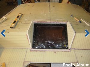
To get some more room in the cockpit I made the seats 175cm long (my body length) instead of the 168cm in the plans. (for nice romantic sleeping under the stars, etc, etc.) After the mounting of the aft cabin hatch it turned out that I've been a little too enthusiastic with the lengthening of the cockpit seats. To make the hatch fit I had to make a cut out in the bridge and that just didn't look very well. The other option, positioning the hatch more aft, is not desirable because of the position of the main sheet track. Repositioning the latter results in less pushing force in the boom to help mast rotation so the mainsheet track dominates the position of the rear of the hatch. To resolve this I've added two extra foam panels to the front panels of the aft cabin which resulted in a correction of 32mm, which is just perfect. Oh well, it seems you shrink as you get older.
Deck laminate and vacuum infusion
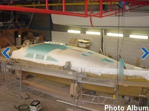
Finally it is time to finish the final structural part of the main hull. This is also the last large vacuum infusion project. After this the hull has become structural sound and finished except for the final post curing. Not to mention the fact that the fragile foam surface now has been replaced by fiberglass with peel ply. Now there is no chance of damage to the surface anymore. A relief.
It is a large bag of 40’x20’ (12x6m) and the infusion strategy is again a simple, uncomplicated set-up according to my now well proven method of central extraction, this time with four single vacuum ports and a resin feeding lines that goes all around.
Vacuum integrity on the outside of the hull, as with the vacuum bag for the bottom, remains much more difficult to get it right than with the vacuum bags on the inside of the hull. But with the help of my wife and son we finally got it right.
When I prepared the construction of this boat I was very concerned about achieving an airtight bare foam hull. Professionals let me believe that this was not possible without the use of a sound mold. Now in hindsight it turned out to be the easiest part and the problems with the airtightness arose especially in the vacuum bag on the outside of the hull.

Bow wing
The plans call for an 75 to 80mm fiberglass or carbon tube. Instead of buying such a tube, I made the tubes myself the easy way, with a foam core (rounded 5 layers of 15mm Corecell)
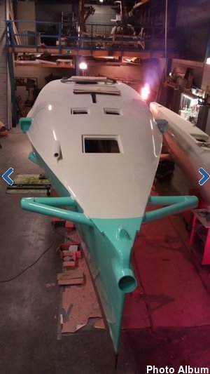
Click on the image on the left to open an extensive photo report of the making of the bow wing.
Anchor gear
Already at an earlier stage, I decided to refrain of the designed anchor locker in the bow. The bow is the worst place to stow a lot of weight, and no locker gives much more interior space. Besides of that, I'm tired of bringing the anchor home by elbow steam so I decided to mount an electric windlass and the combination with the designed anchor locker is not a logical one. It is best to bring the weight of the windlass, chain and rope as far aft as possible. Just in front of the forward sub beam bulkhead is ample space to create a large chain locker and the same space gives also the opportunity to bring the windlass below deck. The consequence is a chain pipe through the deck between bow wing and windlass locker.
An investigation into windlasses taught me that the vertical type is the most suitable for my application . This is because of the space available in the windlass locker and the improved 180 degrees grip on the gypsy with respect to a 90 degree grip on the gypsy of a horizontal winch. An unforeseen problem occurred when I discovered that most vertical windlasses turn clockwise when hauling the anchor. Because the winch will be mounted on the starboard side means that the chaintube comes too far to the outside of the bow wing and the chain must go downwards along the wall of the chain locker. That's not a good setup and I would rather saw a winch that turns counterclockwise at hauling of the anchor. Now all winches can turn both sides, but it is the chainpipe that is fixed on the port side of all vertical windlasses . Only the brand Quick offers a left and right version, but unfortunately only for the larger types (Regal, Dave, Duke). However, the smaller Rider model comes without a chain pipe and an email to the Italian manufacturer confirmed me that I can make a DIY solution for the chainpipe on the starboard side of the windlass.
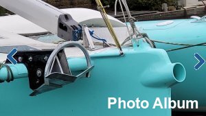
So I purchased the Quick Rider 1000W 24V with 8mm/14mm chain/rope gypsy.
Next question is which anchor to use. I'm familiar with CQR, Bruce, Danforth, FOB and Fortress anchors but the new generation anchors appears to be superior to these traditional models. The various tests prove that Spade and Rocna are the best performers and with regards to their seizing guides I need an anchor with a fluke surface of about 1400 cm², which is a Spade S140 or Rocna 25. A nice feature of Spade is that their 140 model is also available in an aluminum lightweight version.
With their 1:1 patterns I made a wooden mock-up of both versions to determine the possibilities for stowing the anchor on the bow wing. The length of both anchors are about the same but the height of the Rocna 25 is much less than the height of the Spade 140. Last but not least, the Rocna is considerable cheaper than the Spade and the lightweight Spade is far beyond my budget I'm wanting to spent on it.
So I purchased the Rocna 25.
After constructing the bow wing, I also created a rough mock-up for the anchor fitting, where the Rocna anchor must be securely and storm-proof rested. The fact that the base is not straight but tapers from wide to narrow makes it more challenging. A stainless steel structure with sufficient overhang would quickly become too heavy, which is why I opted for a construction in carbon composite. To protect it, I had two stainless steel cheeks made by a blacksmith. These will be embedded within the composite structure. Open the image on the right to view the photo presentation of the build.

Daggerboard construction
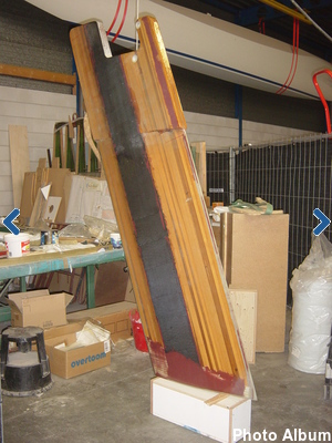
For a long time I thought I was going to make the daggerboard in the same way as the rudder. So, with the aid of a mold. For some reason I have postponed this for a long time. But at the finish of the main hull the appropriate daggerboard case slot must have been created. A good reason at last to make that daggerboard now.
I drop the idea of first making a mold. Instead I make it almost according to the plans, so with a Western Red Cedar wooden core. But to prevent this core in case of a collision with something, or hitting the ground, I made two changes to the plans. First a leading edge with a high density glass fiber inside, instead of the wood, and second a bottom part with a sacrificial foam core. In addition to these changes and for structural reason I replaced the wooden core in the trailing edge by a glass fiber core.
The daggerboard is composed of a rectangular head which remains in the daggerboard case, and a profiled part which projects below the hull. I transferred the specifications of the daggerboard profile to a template and then sawed the core to the right size with a raid saw. I then used the finished daggerboard as a mold to make the airfoil slot in the hull bottom. Photo's are better than explaining by words. You can find them by clicking in the daggerboard image.

Steering considerations
Designer Ian Farrier provides various options for the steering possibilities for the F39. Unfortunately none of these meets my needs.
There are two kinds of sailors. Those who like tillers and those who like wheels. First of all there is the choice for tiller or wheel. Just like everything else to do with boats, the wheel/tiller debate is highly subjective. Both systems have their own pro's and con's. I always had boats with tiller steering. For me this alone is a good reason for a change. One of the advantages of a tiller, the simplicity with only a few moving parts, is not going to work in the F-39 centre cockpit. Like the wheel steering a tiller also needs some kind of mechanical transmission to the rudder stock.
Then there is the aspect of space. The tiller divides the cockpit in a starboard and port part. In this rather small cockpit this compromises access to the coveted space under the dodger. The wheel on the other hand divides the cockpit in a fore and an aft part. The helmsman has is own part of the cockpit. I love that more than a sweeping tiller. Standing behind a wheel while maneuvering in close quarters is imho more comfortable than with the tiller between the knees. Personal taste of course.
So, for me enough reasons to go on with a wheel.
Now what size? a size small enough to walk along is not what I want. In that case I would have bought a sports boat ;) So as big as possible which turned out to be 900 mm. at a height of 800 mm.
As now these basic questions have been answered the next step is the most difficult one. The decision about the transmission system. Roughly there are four basic types, in order of my preference :
- Rack and Pinion steering - sound and straight forward, good rudder feeling;
- Transmission steering - sound and good rudder feeling;
- Cable or rope steering - in my opinion too prone for faults so not for me;
- Hydraulic steering - no rudder feel, also not for me;

Transmission steering system
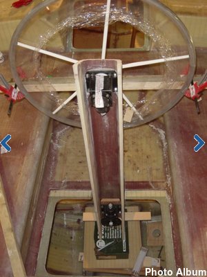
Although I prefer the rack and pinion option this system didn't made it till the implementation stage. The space in the stern is too small and too narrow to make an optimum use of a wide angle geometry. This smart geometry results in a very direct steering amidships (where the loads are low) and a more indirect and powerful steering at full rudder (where the loads are maximal). Also the draglink from pedestal to rudder, with a length of almost 3m. (10ft) , needs a lot of space for its movements and thus a big hole in the aft beam bulkhead.
Enough reason to forget the rack and pinion system.
Whishing to maintain the wide angle geometry I decided to change over to a transmission steering system and choose for the Danish Jefa system. This system is based on the same principals as the rack and pinion system; the rotation of the wheel is transferred to a push pull movement. Not trough a draglink but trough a torque tube via a gearbox and levers.
However, also due to the limited space behind the transom, the proposed position of the bevel reduction gearbox is too far aft with the consequence that the position of the torque tube doesn't match with the height of the cabin bed. The torque tube is intended to go underneath the bed bottom which space is also reserved for the water ballast tank.
The solution is to position the whole rudder 96 mm further forwards. This means that the wideness of the lower step in the stern has to change from 374 to 278 mm. Resulting in a 210 mm. extension of the reduction gearbox shaft. The bevel reduction gearbox is housed in its own watertight compartment and separated from "outside" by a watertight roller bearing. The connection of the autopilot drive is at the front of the bevel box right under the steering pedestal. The autopilot drive will be ordered at a later moment.
I have high expectations of this steering system. The only drawback I can think of is the considerable weight of the bevel reduction gear box that far behind in the boat.

Rudder construction part one, the rudder blade
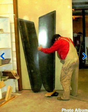
During the construction of my boat, I have gotten a lot of relationships with other boat builders, both domestically and abroad. The exchange of experiences has proved extremely valuable and is also one of the many fun incidentals of such a DIY project. Here in the Netherlands are two fellow boat builders who are both involved with CNC technology. Bert (F39) as a professional and Nico (F82SR) as a hobbyist. The fabricated parts and the mold for the daggerboard are being made by Bert. And just recently Nico offered to make the two rudder plug halves for my F39. Nico is an airline pilot and spent his lonely days somewhere far away in a hotel room on the programming of hundreds of lines in the CNC software for my F39 rudder. Great job Nico and thanks again. After finishing the rudder blade mold, it is not much extra work to make a spare rudder blade. So, I've made two rudder blades.
Rudder construction part two, the rudder sleeve and case
Designer Ian Farrier provides various options for the rudder system. The main choice is between the underslung rudder (not shown in the drawing) and the daggerboard style rudder. I prefer the latter as this system gives a better steering control for getting in and out shallow waters as it can be raised up and down.
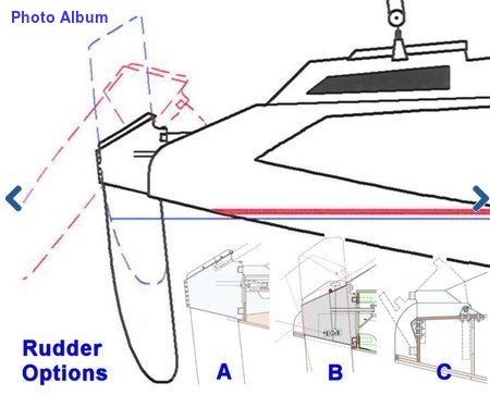
The daggerboard style rudder system comes in three variations, in this drawing called A, B and C. The difference is in the manner in which the rudder blade kicks back should any object be struck.
The rudder option C with the hinged rudder box is only suitable for a steering system with cables and therefore not suitable for me because it does not fit in my chosen transmission steering system. After all, this system requires a fixed connection to the steering arm of which position is not affected by a pivoting movement.
The rudder option B is my preferred rudder system and consists of a two-piece pivoting case and sleeve. Should any object be struck or the rudderblade hits the bottom, the aluminum rudder lock bar will break, allowing the rudder to kick back preventing any more serious damage.
Rudder option A is much simpler but will not kick back should any object be struck. However, the case should split apart down the aft edge (with aluminum bolts sheering) to allow rudder blade to kick back without any damage to the transom. But some damage to the rudder case is likely to occur, which I can confirm from my own experience which such a system on a F33. Due to the simpler construction this will become my backup and emergency system.
I have made two rudder blades for redundancy reasons and for the same reason I make both rudder case options B and C. B as the main system and C as a spare system in case of a fatal rudder damage. No, I'm not traumatized over the incident with the F33 rudder but better safe than sorry, especially in the open ocean. Two complete systems it will be.

Steering pedestal
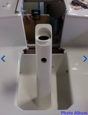
The considerations of a self-builder are sometimes inscrutable. It would have been much easier if I had just bought the steering pedestal ready-made. I underestimated the amount of work and it took me a long time and effort to make it to my liking.
At first I had wild plans to design my own but at the end I just copied the type 150 of Jefa. And with this I made a huge mistake. Not that the jefa is an inappropriate model, on the contrary, but the Jefa tube is an aluminium tube with a wall thickness of about 3mm. or so while my composite construction has a wall thickness of about 20mm. While overlooking this fact and maintaining the same outside dimensions I made it for myself quite difficult. The dimensions of the bevel boxes with their flanges requires now extra recesses in the foam.
The main reason why I chose for the home made steering pedestal is the assembly of the autopilot beneath the cockpit floor. The bevel box that connects the vertical torque tube in the steering pedestal and the horizontal torque tube to the reduction gear box is also the base for the autopilot drive. The bevel box needs a sturdy base in a position somewhere above the engine. Instead of having to make all kinds of auxiliary constructions above the engine (various solutions are thinkable), I choose to extend the steering tube and have it stuck through the cockpit floor to provide a solid basis for the autopilot. As a nice side effect, the steering column is now a rock-solid post in the cockpit and the passage in the cockpit floor is absolutely waterproof.
All in all the result is very satisfying

Water ballast tank
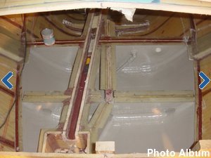
The aft part of the F39 must be kept as light as possible so no storage in that area. However, when running downwind in big seas and strong winds some more weight in the stern is desirable. Actually I don't know if I need extra ballast in the stern and will encounter such circumstances, but in this stage of the build and with just a little extra effort I have the opportunity to make a sea water ballast tank in a further not usable part right in front of the transom. I guess that the maximum content of the tank will be about 500 liter.
Aft cabin interior
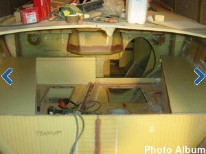
Access to the aft cabin is still easy through the open transom. In building the interior of the aft cabin I have take advantage of this stage as much as possible. The work was quite complicated because of the routing of the transmission steering components and my wish to have a waterballast tank at the front of the transom. On both sides of the cabin I have made cupboards.
Finishing the stern

I have been a long time puzzling how to end the stern of the boat. Although I admire Ian Farrier very much, the design of all F-boats looks a bit bleak from the back. The cause of this is the two windows in the stern. Of course, that is all a matter of personal taste. But I do not like it and have come up with a different solution that better suits my other needs.
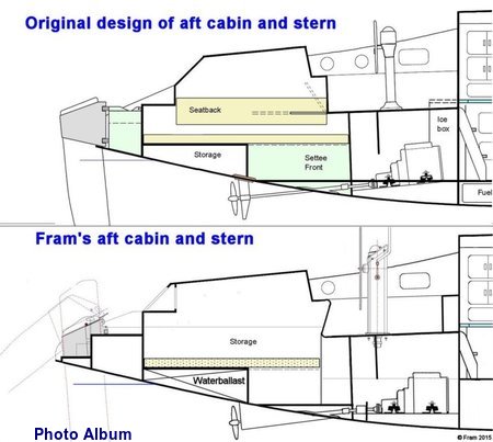
In the original design it is a too big step from the stern platform to the aft cabin roof. In fact, a step is missing in between. On my wish list was also a virtually rainproof portlight in the stern, of course rainproof when it is open for ventilation. In order to achieve this, the portlight must be mounted under a kind of awning. Now I have realized this by integrating an extension of the cabin roof with an extra step in the transom.
Another wish that I had was that the rudder is more or less being protected by the hull. With the realization of a larger scoop it was also possible to include an additional step in the stern. The necessary extensions of the hull and the roof of the aft cabin were realized in a much earlier stage. I had all these changes already in my mind during the construction of the hull.
And a bonus not to be underestimated is that the aft cabin has become much more spacious by this change.

Postcuring
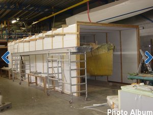
I have been waiting for the summer for a sufficient room temperature to undertake this process. The infusion resin used by me must be post-cured at a temperature of about 80 degrees Celsius for 8 hours. That is quite a lot to achieve by simple means.
Together with my son we have built an "oven" consisting of 100 mm. polystyrene sheets encased in prefabricated particle board H-beams. Making these H-beams was a -quick and dirty- job which resulted in the collapse of the roof. The fixing method with (too small) staples did not appear to be resistant to the high temperature. 60mm. screws did a better job. This was actually the only setback and the rest of the process went very well. Two diesel heaters at both ends of the box together with a workshop room temperature of 25 degrees were sufficient for the desired 80 degrees Celcius oven temperature.

Fairing and painting
I am very happy with the final appearance of the floats. The fairing and painting job turned out great thanks to the thoroughly preparation and lots of effort in the putty and sanding process. However, the fairing of the hulls with the fairing board was a time consuming and very tough job, to be honest, a hell of a job for which I am getting to old().
With the purchase of two wide flexible filling knives at Flexisander, one 2' wide (600mm) and the other 4' wide (1200mm), I now choose for a different approach for the filling, fairing and sanding process of the main hull.
 My goal is to minimize the hard work with the long fairing board and maximize the use of my sanding machines. The trick is to shape the fairing compound with the long filling knife in one continuous stroke, preventing excess fairing material and when done to not touch it anymore. The next part to shape is the width of the putty knife apart. After (partly) curing it is the turn for the parts in between. When finished this is the first layer of faring compound. The second layer, which uses much less fairing compound, is thereafter applied in such a way that this is overlapping the first areas.
The whole job has been done with the 4' wide knife which gives a very fair result and minimize excess fairing compound. The use of the random orbital sander with grid 40 sanding paper is now mainly in order to make the surface more smooth. This requires some skill to avoid sanding to deep. The last step is the overall fairing with the long flexible faring board. As the hull is already very fair this is not much work anymore. My last step of the fairing process is applying one final layer of a fine finishing fairing compound which smooth out the grid 40 sanding strokes as well as the last imperfections. The last part of this finishing process is sanding down the last fine layer of fairing compound with grid 120 and apply the high build primer before finishing with the two part high gloss fairingandpainting.
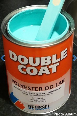
About the color ..... Mint Green ..... It is a bold color and provoked divided reactions. However, somewhere in the nineties I came across a boat (the 40ft. monohull " Epoxydus" that very much impressed me. It was mint green with a white deck. I loved it. Since that time I have that color in my mind and now I have the opportunity to make that true for my own boat. Only the crew needs some more time to appreciate it ...... ;-)

Three hulls coming together
The final assembly of my trimaran. The transformation of three hulls and four beams into a boat is the climax of the construction. Finally everything comes together and leads to the trimaran I dreamed of. It is definitely a highlight of the construction so far. But first to do is bringing the floats down to earth. It's been a long time since we hung the first float under the roof, followed by the second one. All those years they have collected only dust but now they can come down again.
The port float is hanging above and behind the boat. To bring down the port float I first had to make room next to the boat. The boat has to slide sideways to create ample maneuver space for the forklift. With the help of two pallet jacks the boat easily slides sideways. With a makeshift boat-stand clamped to the forklift I carefully lifted the float, unscrewed the tensioning straps the floats were hanging in and bring it down.
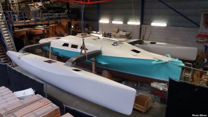
However, maneuvering with forklift and float only takes one way. The port float is still looking in the wrong direction but turning is not possible because of lacking space. The workshop crane brings the solution. In the free space somewhere in the middle of the workshop height, I can turn the float in the right direction and bring it back to the position at the port side of the main hull.
Fortunately the other float is much easier to reach and is already hanging in the right direction. There is still not enough maneuvering space for the forklift but taking it over by the workshop crane brings the float to its position at the starboard side of the center hull.
This phase of the build is also the moment of true. All parts that are built separately from each other now come together. I have had sleepless nights about the alignment of the beams and folding system. During the build there was not one moment to check this, only by rough estimates. After all there is not any adjustment possibility in the solid carbon anchors.
Mounting the first two beams on starboard was indeed an exciting moment. Fortunately all my worries have proved unnecessary. There is practically (only a few milimeters) no deviation in the alignment and that is a huge relief. Again kudos for designer Ian Farrier
Putting the boat together, however, also involves a lot of difficult laminating work. Laminating the rear of the aft beam sleeve must be performed through the small hole of the inspection hatch on the aft deck. Using my cell phone in camera mode and wrapped in clear plastic, I have some insight into the laminating work on the underside of the sleeve.
The work that I hate the most is upside down lamination. There are still six locations in these narrow floats where I can qualify myself for this great work. Preparing all tapes saturated with epoxy, take the wet mass in the right order to the small workplace and then in spite of the gravity applying the patches above your head, meanwhile staying clean of the falling epoxy drops, quite a party.
I did one of these works on Christmas Day 2017 and made a video of this party, enjoy!

Next phase
With these last laminating jobs Fram is ready for the next phase of her construction and she leaves the workshop that has been home for the last 8 years. Launching and christening are planned ambitiously and further completion will take place while floating in the water of her home port.

| « Previous Next » |
