Fitting out.
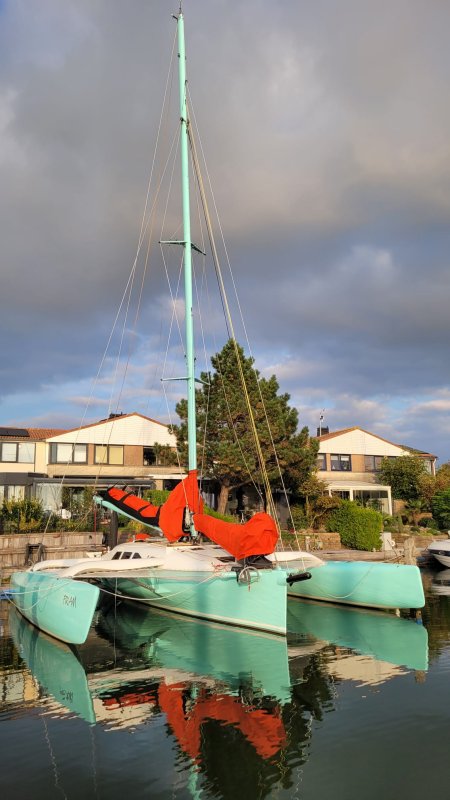
In this chapter, I will describe the fitting out and further equipment of Fram. It's an ongoing project. This chapter will be further updated as the work progresses.
Mainsheet traveler.
The original plan was to create a circular mainsheet traveler with a radius approximately equal to the length of the boom. When I was building the roof for the aft cabin, I replaced the foam at that location with hard foam. You can find the photos in the album related to the preparations for the deck laminate.
However, in the end, I found it to be too complicated, too much work, and too expensive, especially considering the minimal benefits. I didn't think it was worth it.
Afterward, the plan was to simplify everything drastically by implementing a so-called "Oceansheet." This is a sort of inverted V-shape with three-block tackles on each side of the cockpit. This is a solution that several multihull sailors use successfully. However, I do see some disadvantages when it comes to easy trimming.
For a long time, I assumed that I would go with this simpler option, accepting the drawbacks. However, the forces under such a block near the cockpit are quite substantial, and when I saw how the laminate under such a block on an F-36 trimaran was deforming, it became clear that additional reinforcements in that area were necessary. Work I hadn't initially anticipated.

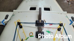
In the end, it became a straight and more traditional traveler. For its base, I purchased 7 Red Cedar boards measuring 1.8x14x305 cm. There was enough material to build the traveler for the High Aspect Jib as well.
I drew the pyramid cross-section on a piece of paper, wider at the base and narrower at the top. As it goes further down, the base becomes wider than the width of the boards, but by clever cutting, I fill that in with what I cut away from the upper, narrower layers.
The track is from the Ronstan Series 30 with a standard length of 300 cm. I maintained that length so that a portion of the traveler extends beyond the roof of the aft cabin. Please click here or on the image to open an extensive photo report.

Jib boom traveler.
One of the great advantages of a trimaran is that it is more than an excellent sailboat concept, you could say it's a sailing machine. In order to fully exploit that as a short-handed crew or solo sailor, the systems must work perfectly and be easy to use. From the outset, I wanted, among other things, to have a self-tacking jib for this reason. Tacking frequently in narrow waters becomes child's play with it.

Ian Farrier has provided such an option, but he associates it with the need for a centerboard. A daggerboard, in his design, protrudes above the deck and in front of the mast. Right in the place where a self-tacking jib's traveler track is normally positioned. A centerboard does not extend above the deck and thus does not obstruct the traveler.
For me, the advantages of a centerboard do not outweigh the disadvantages. That's why I consciously chose a daggerboard. I solved the "problem" of the daggerboard protruding above the deck by placing the jib's traveler track in front of the daggerboard case. To ensure this doesn't compromise a smaller jib, I equipped it with a boom, a "jib boom," in other words. In fact, this makes the trim options for the jib the same as those for the mainsail.
Another option could have been to widen the space just in front of the mast step by making adjustments to the mast step and the head of the daggerboard. I didn't want to do that, especially since I want to experience the practical benefits of a jib boom.
The downside to the jib boom is that it does make the foredeck a cluttered and unsafe place to be, but I ensure that I don't need to be there and can trim everything from the cockpit. In addition, I ensure that the boom can be well controlled under all conditions with the jibsheet, topping lift and the traveler control lines.
I carried out the construction parallel to that of the mainsheet traveler, and the structure is the same, although lower and narrower. The Ronstan Series 30 track is 2 meters long. Please click here or on the image to open an extensive photo report.

LiFePo4 Battery
First and foremost, I am not an electrician. What I know is what I once learned in school during my youth. Of course, that knowledge has faded over time. However, the good news is that, recently, I’ve come to understand the difference between volts and amperes again ......
With this background, I had the idea to build a LiFePo4 battery. I deliberately did not buy a ready-made LiFePo4 system, also known as a "drop-in" battery. I wanted to assemble the battery myself from individual cells, which allows me to understand the technology and tailor the system entirely to my needs.
The concept is simple. Due to the high power (11kW) of the Jet Thruster onboard, I want a 24V service battery that is capable of discharging at 3C (3 times the capacity of the battery). That’s quite a lot. This led me to the required battery capacity of 300Ah at 24V. That should also be enough to have a comfortable onboard system with adequate capacity.
LiFePo4 cells have a nominal voltage of 3.2V each. So, I needed eight of them. Based on these parameters, I came across the Winston brand cells. It’s been a few years since I purchased them, and there wasn’t much competition back then. Nowadays, there is a wide range of cells available, and they’re relatively cheap. Prices are even still going down.
It’s a good thing that these cheaper versions weren’t available back then. I might have chosen them. But, now that I have more knowledge on the matter, it turns out that I unintentionally made the right choice. The current best-selling cells are not equivalent to the quality and capacity of the Winston cells. They allow a maximum discharge of only 1C or less. They are smaller and lighter, however, which is a good quality for a multihull.

When building the interior, I had to consider the placement of the battery. That’s why I bought the Winston cells early on. They sat unused in the garage for a few years after that. There were too many other priorities related to building Fram. The intended place for the battery is at the bottom of the crossbench in the dinette. It is well-protected there and close to the center of gravity of the boat. And just as importantly, very close to the Jet Thruster for the shortest possible wiring.
It took me a while to get motivated to dive into the LiFePo4 world. Or, as I call it, the “LiFePo4 Soap.” Forums and YouTube became so complicated and contradictory that I quickly lose sight of the bigger picture. What was essential for one person seemed to be lethal for the battery for another. Even suppliers contradicted each other. It was enough to make one lose hope. In the end, I determined a few simple and understandable principles for myself from all that noise:
• Initial charging with a maximum of 3.65V per cell (the manufacturer says 4V);
• Install a BMS (Battery Monitoring System) to be able to monitor each cell (for my own peace of mind but in hindsight not stricktly necessary);
• A maximum total charge of 27.6V for the whole battery;
• No trickle charging, i.e., 0.0V when sufficiently charged;
• Implement a limit to prevent deep discharge;
• No charging in freezing temperatures (although Winston claims it’s fine);
• To prolong lifespan, don’t store fully charged when not in use;
• A DC-DC charger between the start battery and LiFePo4.
The DC-DC charger (although there are other solutions outside of my understanding) in the LiFePo4 setup, is primarily designed to prevent overloading of the engine’s alternator. In my case, it also serves to convert the 12V from the alternator to 24V (27.6V to be precise). As a third consideration, there is still an old-fashioned start battery that ensures the well-being of the alternator.
To gain a better understanding of the system and increase my knowledge by doing, I set up a test setup in the living room. It’s a replica of the intended installation onboard. The engine’s alternator was simulated with a lab power supply, and the user was simulated with a 100-watt lightbulb powered by an AC (220V) converter. With the computer connected to the DC-DC, I was able to test various variables.
First, the initial charge of the cells. The serial numbers of the eight cells are consecutively ordered, so they come from the same batch. All eight came from the factory with a 3.28V state of charge. Using a lab power supply, I charged all of them individually to a constant 3.65V. This took about one week (turned off during the night). I then connected the cells in parallel to form one 3.2V 2400Ah battery and charged them again to 3.65V. That only took about ten minutes, after which I let it rest for a while. After that, I connected them in series to form the desired 24V 300Ah battery.
The energy storage in these cells is phenomenal. To avoid any accidents, you must prevent short circuits at all times. I know myself too well in this regard, so I bought an insulated wrench to tighten the M12 studs and nuts on the battery terminals.
Next, I completed the setup with a power supply, charger, converters, and a load. I spent about three months experimenting to get to know the ins and outs of the system, keeping it almost continuously in my field of view in the living room.
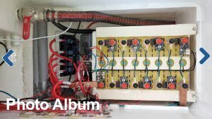
Once I felt confident that I understood how it works and what measures were necessary to keep it running smoothly, I dismantled the setup and installed it in the boat. The place for the battery is at the bottom of the crossbench in the dinette. Everything is well protected under a removable floor. This space is ideal for storing supplies
Connecting the Jet Thruster, with its very high current and thick wires, was a time-consuming precision job. It works well now, but it certainly took quite some effort.
But that’s a story for the next chapter.
To be continued


 .... To be continued ....
| « Previous Next » |