Main hull construction ²
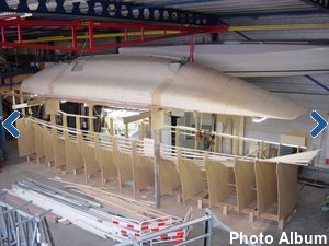
(continued from page [ 1 ]Arrived at my new construction site! Fitting out the new workshop turned out to be much more time consuming than anticipated. But now everything is in accordance with my wishes and this weekend I had the feeling to continue the boatbuilding again instead of all kind of other things, like organizing and cleaning up too much company materials, dragging along too heavy girders, hoisting and mounting too heavy winches, organizing and connecting too much electrical wires, building and pulling down again an incomplete scaffolding, which despite some missing components was strong enough to hold up the main hull half for a while, which by the way wasn't necessary if I had done the electrical winches first, etc.
And suddenly, while the building was closed, a security guard was behind me. I was shocked. He appeared to have been alarmed by the neighbors who had worried about the sounds they heard. Normally no one is here on the weekends.
Oh well, the social control has worked in any case ...
Setting up the second main hull half
Again a fun part to do. Working in the new workshop looks to be much faster due to more space, better equipment, less distraction and less socializing .....
And now there are a lot of critical observers (i.e. colleagues). No doubt they will inspect the work on Monday morning to discuss the working rate of their “boss” ..........

Boatbuilding again
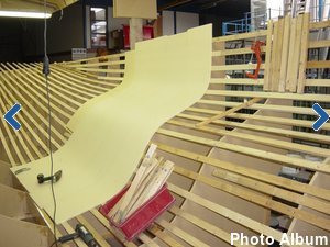
After having built five hulls, this last sixth hull has become a more or less routine job. In the spacious workshop I now only need a few days to build the basic foam hull. The construction method with the vertical foam strips works easily and quickly. See also the photo gallery and video.

Vacuum infusion of second main hull half
The handling of all the glass and vacuum materials is now much more convenient in this spacious workshop. However, in my enthusiasm I forgot to add some reinforcements in the window area and the area of the anchor locker. While writing this, the inside of the hull has been covered with the vacuum materials except the vacuum bag. Next weekend I have to fix that .......
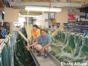
On one of the hottest days of the year (Saturday July 11 2010) the vacuum infusion of the second main hull half went flawlessly. I few hours before I was desperate not being able to find a big leakage in the vacuum bag. At first I thought having found the culprit, a forgotten connection of a vacuum line. But after I repaired that nothing changed.
To be able to hear better, I put the vacuum pump outside the building, however I knew that the leak was probably too big to be able to hear. I spent the whole Friday evening and Saturday morning on finding the leak. All kinds of scenarios went through my mind, including the worst, a poreus or a punctured hull. Just before I thought I was getting crazy, I noticed the cleaning lady who was still in the building on this Saturday morning. Knowing that women are much more patient, I asked here to help me finding the leak.
After 5 min (!?) she found a small leak in the bag. Unfortunately nothing changed when I closed it with a piece of tacky tape. Some minutes later she found the real wrongdoer, a big square in the bag, hidden in a pleat. She made my day! Thanks Angela! Now, I got some vacuum and the rest of the leakages were easy to hear and I even finished with a perfect bag.
The drop test (vacuum pump off) resulted in a not worth mentioning loss of vacuum. Room temperature was 32° Celcius and so was the resin. Just perfect for a fast infusion. Click on the image at the right for the photo gallery and the video of laying up the dry fabrics and infusion of this mainhull half.

Port side folding system setup and placing beam bulkheads
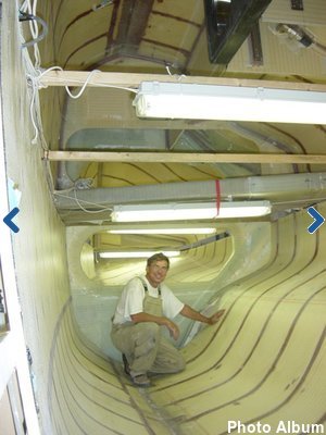
When working on the starboard half I made all the carbon lower folding strut anchors, but not the complete anchor assembly for this port side. So, before putting in these carbon anchors, I first had to do some unfinished business on the carbon anchors. Cook them in the oven (this time not the one in the kitchen) and making the total anchor assembly.
Maybe it looks like I always have the things under control. But that is only apparent and silly mistakes are indeed made. After I freed the two carbon anchor assemblies from their vacuum bag and was preparing to mount the assembly in the hull, I discovered that the base plate was shorter than the anchor….. F**###(censored) In a fit of madness I had the base plate mounted in the wrong direction. Itself is not so bad were it not that all the UD fibers are now running in the wrong direction. Too bad of all the beautiful laminate work (and a waste of three days).
There is a lot of laminating work to do around the beam bulkheads with up to 20 layers of UD fabric in some areas. This construction looks to be real solid and bullet proof. As the lamination and bond to surrounding areas is critical I try to be even more meticulous in this area.

A milestone, Starboard meets Port
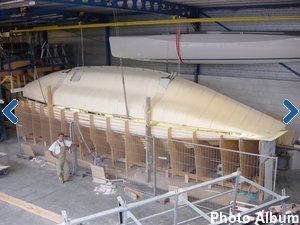
Here are some photo's of the joining of the two main hull halves. Overall the hull halves fit very well together without noticeable misalignment. On Menno's Blog (Dutch F22 boat builder) I saw he used the two top battens to align both hull halves. Great idea (thanks Menno) because these battens make the use of clamps possible, which is much easier than bungling small wood pieces and screws.
I made this second (Port) main hull half a little longer in the stern. This was not possible in my previous workshop due to the lack of space. After joining the two halves I decided to make an extension to the Starboard half to make both hull halves the same length. I don't know yet if I will make the hull one feet longer, but doing this now in this stage is quite easy and I can always decide afterwards to cut it off.
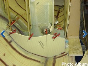
More bulkheads and details in the port side half
I made all the other bulkheads in this port side after the joining of both hull halves as aligning is much more easier this way. In the bow area I made the preparations for a second carbon chainplate. This is placed at the front of the anchor well and is intended for a heavy weMore bulkheads and details in the port side halfather jib or storm jib. Since this is not a design feature, I've created my own solution. All the "thinking" about the cockpit coaming and shelves in the cockpit area has been done in the starboard half, so copying this to the port side was now done in just one weekend. For now the inside parts of the mainhull are finished and next is removing the frames and turning the hull upside down.
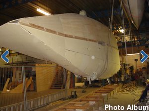
Freed from the mold frames:
A milestone again
A long weekend of preparations with among other things unscrewing 7500! screws.
The big event, hoisting the hull and turning it upside down, was done in the next weekend. I like to do this on my own, without onlookers, no hurry, good thinking and easy going with the help of the four electric hoists in the ceiling. The hull is now ready for further work on the outside.
You can find the photo's and video by clicking in the picture.
Bow pole tube with carbon chainplate
At first I thought of making the carbon bow pole by myself, also as a kind of exercise for making the carbon mast and boom in future. But for practical reasons I decided to buy a custom made bow pole, to save on time and to have a look in the kitchen of a professional carbon mast maker. Thomas Whilkes of Ceilidh Composite Technologies (www.carbonmasts.com), the maker of the carbon bow pole, was so kind to discuss some ins and outs with me about making a carbon mast and the ideas I have to do this by myself.
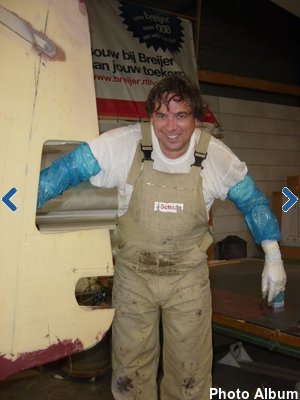
The bow pole has been made in a female mould with carbon pre-pegs. The only thing I still have to do is making the attachment points for screacher and spinnaker. The bow pole is retractable and slides through a bow pole tube. To make the bow pole tube I thought I needed the bow pole as a mould, but in hindsight it was not necessary to buy the bow pole in this stage, as the outside diameter is exact the same as a 125mm pvc drain pipe. So, instead of the carbon tube I used a pvc drain pipe as a mould for the bow pole tube. With 7 layers of wallpaper I increased the diameter to 128mm for the easy gliding of the bow pole. The mould is finished with two layers of plastic film and a Teflon coat between the films to be able to release the glassfibre bow pole tube from the mould.
Mounting the compiled bow pole tube and carbon chain plate proved to be a difficult job in a hard to reach place. After ample consideration I had to conclude that an access hole had to be made in the bow. That hurts and to make it even worse a second access hole followed. And a third ...... At the end there was not much left of the so carefully made bow. After the assembly of an at least as awkward bow pole tube bulkhead the bow has been restored in her previous full glory.

External laminate from gunwale to keel
Before laying up the external laminate, various “small” other jobs has to be done . Every time it is amazing how a relatively small job takes much more time than expected. For example the beam recess on the outside of the beam bulkhead. For cutting this recess area to size and removing superfluous foam hull parts I needed all the cutting and sanding tools I have.
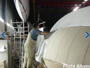 Jig saw, reciprocal saw, multicutter tool, dremel tool, powerfile, belt sander, angle grinder, powerplane and the handtools like chisels, grater, hammer, file, multiknife, sandpaper, etc. and this all within 5 square ft . The four beam recesses took me two days with a lot of itch (from the glass dust) as a result. Then some foam fill pieces, which took another whole day. Everything is taking at least three times longer then expected .....
I made a little change in the lay-up schedule of the external laminate in the bottom of the hull. The plans specify an extra glass 0/90 layer in the bottom of the hull, for abrasion purposes and also for the balance between the 0° direction of the fibers inside and outside. As an alternative I've used a 45/45 Aramide (Kevlar) layer as the abrasion qualities of this type of material is superior compared to glass. The topside of the Aramide fabric is covered with a thin CSM layer, so the outside surface is glass and not Aramide. To compensate for 0° direction strength I've also added a line of glass UD in the opposite position of the internal UD layers. All in all a little heavier than specified, but good for peace of mind ....
In the mean time I'm playing with the RTM-Worx software, on the one side to make the 3D model (that's fun) and on the other hand filling the model with material qualities like resin viscosity and fabric permeability (that's just a puzzle to translate in a lot of data)

Controlled Vacuum Infusion of mainhull bottom
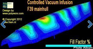
I can say I now have a lot of experience with making airtight vacuum bags. As a matter of fact, within this project this is big hull vacuum bag number 9 and I thought it would be a piece of cake. After all, it is not just a vulnerable foam hull anymore but a foam hull with an airtight internal laminate. And the joins of the Port and Starboard halves are covered with a glass tape. So no worries about air tightness. I thought ........
Unfortunately this assumption proofed to be very wrong. I did some stupid things, as using too long temporary screws here and here. This area was also not air tight. Further more it seems there were air channels in the UD fibers running from the outside to the inside in the forward beam bulkhead flanges. In short, it became a headache vacuum bag, in fact the worse one I've ever made and it took much too much time to get it right. As the infusion of the hull was planned and I had appointments with some helpers I worked a continues 40 hours to get it right, but unfortunately the bag was not good enough to start the infusion. A disappointment for everyone and I had to cancel the event.
Two weeks later it had to happen! After some more changes (read four 8’ extensions to get more space around the beam flanges) in this very recalcitrant vacuumbag and further improvements of the hull vacuum integrity. Despite the fact the third version of the vacuum bag was still not perfect the infusion started at 3.00 PM in the afternoon. As usual, there was a lot of interest from colleagues and friends. There were a few precautions taken to be able to solve possible problems during the infusion and this has worked out satisfactorily. Only the end counts and despite the troublesome preparations it was again a success, a big relief and another milestone in the project. After an evening and night watch during the cure of the resin I went home at 5.00 AM the next morning, tired but with a good and happy feeling.

“Upside down” interior work
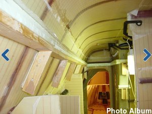
While the hull is still in an upside down position, it is still a convenient moment to make the fillets or flanges that supports the horizontal parts in the interior, loke the cabin floors, settees, bunks and chart table.
Looking for a material that is able to follow the hull shape and in the same time remains horizontal, I found Styrodur insulation foam to be the suitable material. All positions are marked with a laser and the mold is formed by the Styrodur which is supported by temporary pieces of wood. Because of the light weight of the Styrodur it is easy to fix with a 3M glue spray.
Now it is also the right moment to make the cabinroof reinforcements on the inside. Working on my knees is easier than working above my head.

Turning the hull upright
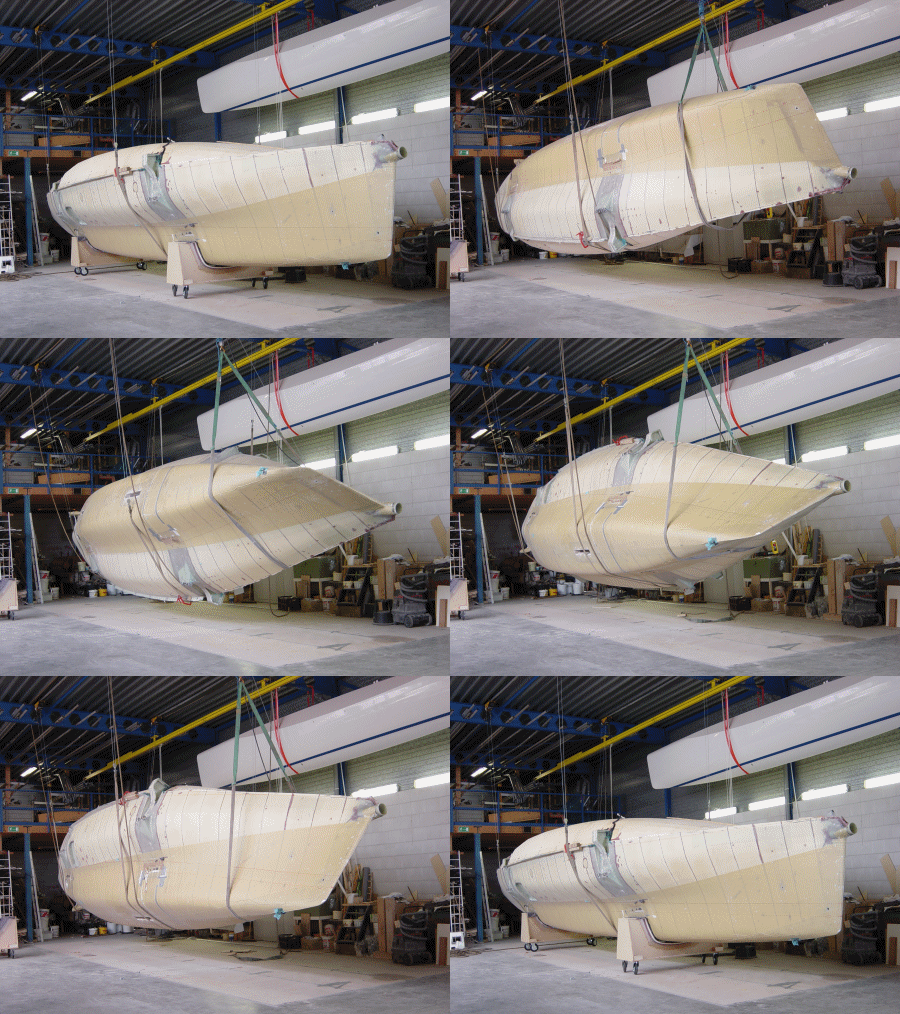
Turning the main hull upright is once again a milestone in the project after which a new phase in the build starts. Click in the animated image to open the photo gallery.
Farewell strong back, the base construction on which all the hulls has been build, is now demounted in little pieces and removed to the dumpster. With my four electrical winches under the roof of the workshop, the actual turning went flawlessly.
Of course I did it alone again and to continue to fully concentrate without prying eyes of others. With some extra ropes and the back-up of the workshop crane I took enough safety precautions to avoid any risks.

The next phase in the construction of Fram begins. For the support of the hull in the next phase of the construction I've build two mobile boat stands. I used the hull as the mold for the two boat stands. For the subsequent assembly of the mainhull and the two floats the boat have to be more or less moveable without too much of a hassle.
| « Previous Next » |